

What Is the Difference Between a 90 and 45 Face Mill?
Date:2025-12-24Number:2241When it comes to precision machining, selecting the right cutting tool can make or break a project. Among the most commonly used tools in milling operations are face mills—specifically, the 90-degree and 45-degree variants. While both serve the fundamental purpose of creating flat surfaces, their geometries, applications, and performance characteristics differ significantly. For professionals working with carbide end mill cutters, understanding these differences is essential for optimizing tool life, surface finish, and overall machining efficiency.
In this comprehensive guide, we’ll explore the functional distinctions between 90° and 45° face mills, delve into their ideal use cases, compare chip evacuation, cutting forces, and rigidity, and explain how your choice impacts compatibility with modern carbide end mill cutter systems. Whether you're a seasoned machinist or a manufacturing engineer sourcing tooling for high-volume production, this article will equip you with actionable insights grounded in real-world shop-floor experience.
At its core, the difference between a 90-degree and a 45-degree face mill lies in the lead angle—the angle at which the cutting edge contacts the workpiece relative to the feed direction.
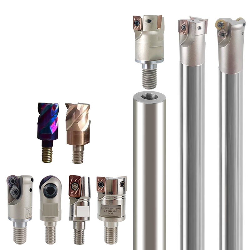
A 90° face mill (also called a square shoulder mill) has inserts mounted perpendicular to the axis of rotation. This means the cutting edge engages the material straight on, producing a true 90° wall with no draft.
A 45° face mill features inserts angled at 45 degrees to the workpiece surface. As a result, the cutting action is more shearing than orthogonal, distributing forces differently across the tool and workpiece.
This seemingly subtle geometric variation has profound implications for vibration control, power consumption, surface quality, and toolpath strategy.
One of the most critical considerations when choosing between these two face mill types is cutting force distribution.
With a 90° face mill, nearly all cutting force is directed radially into the spindle and workpiece. This creates higher radial loads, which can lead to chatter—especially on less rigid machines or thin-walled parts. However, because there’s minimal axial force, 90° mills are excellent for maintaining dimensional accuracy on shoulders and edges where squareness is non-negotiable.
Conversely, a 45° face mill redirects a significant portion of the cutting force axially (along the spindle). This reduces radial deflection and minimizes vibration, making 45° mills far more forgiving on older or lighter-duty CNC machines. The shearing action also requires less horsepower, which is advantageous in energy-conscious or high-throughput environments.
Pro Tip: If your shop runs mostly VMCs (Vertical Machining Centers) with limited torque or older spindles, a 45° face mill often delivers smoother operation and longer insert life—even if your part doesn’t strictly require angled walls.
Surface finish is another area where the two designs diverge.
A 90° face mill tends to leave a slightly rougher finish due to the abrupt entry and exit of each insert into the cut. Achieving a fine surface often requires reduced stepover (typically 30–40% of cutter diameter) and slower feed rates—increasing cycle time.
The 45° face mill, thanks to its oblique cutting action, produces a naturally smoother finish. The overlapping cut pattern from adjacent inserts creates a more uniform scallop height, allowing for higher stepovers (up to 60–70%) without sacrificing surface quality. This makes 45° mills ideal for large pocketing or facing operations where aesthetics and flatness matter more than sharp vertical edges.
For shops using carbide end mill cutters in finishing passes after roughing with a face mill, pairing a 45° rougher with a precision carbide finishing end mill can yield exceptional results with minimal handwork.
Chip formation directly affects tool life, coolant effectiveness, and automation reliability.
90° face mills generate short, thick chips that tend to curl tightly. While manageable in dry or mist-cooled setups, these chips can pack into corners during deep facing or slotting, increasing heat buildup and risking recutting.
45° face mills produce longer, thinner, and more fragmented chips that evacuate more easily—especially when paired with through-spindle coolant or air blast systems. This is particularly beneficial in automated cells where chip clogging can trigger unexpected downtime.
Modern carbide end mill cutter systems often integrate chip-breaker geometries optimized for specific materials (e.g., aluminum vs. Inconel). Similarly, face mill insert design—including rake angles and edge prep—must align with your material and coolant strategy. Always consult your tooling supplier’s recommendations based on ISO material groups.
When to Choose a 90° Face Mill:
Machining parts requiring true square shoulders (e.g., fixture plates, die blocks, hydraulic manifolds).
Working with pre-hardened steels or exotic alloys where minimal axial force prevents part distortion.
Performing light finishing passes where dimensional tolerance on vertical walls is critical.
Using carbide end mill cutters for subsequent profiling—you need a perfectly flat reference surface with sharp edges.
When to Choose a 45° Face Mill:
High-efficiency roughing or semi-finishing of large surfaces (e.g., mold bases, aerospace structural components).
Running on less rigid machines or tombstone setups where vibration suppression is key.
Machining ductile materials like aluminum, copper, or low-carbon steel where chip evacuation is challenging.
Prioritizing tool life and throughput over absolute edge squareness.
Real-World Example: In automotive transmission housing production, a 45° face mill is often used for initial bulk material removal due to its stability and chip control. Final squaring of critical mounting surfaces is then handled by a 90° face mill or a dedicated carbide end mill cutter with tight runout tolerances.
Today’s modular tooling ecosystems blur the lines between traditional face mills and advanced carbide end mill cutters. Many manufacturers now offer hybrid solutions—such as 45° face mills with indexable carbide inserts that mimic the performance of solid carbide—but at a fraction of the cost.
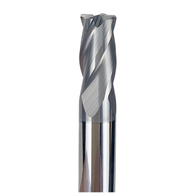
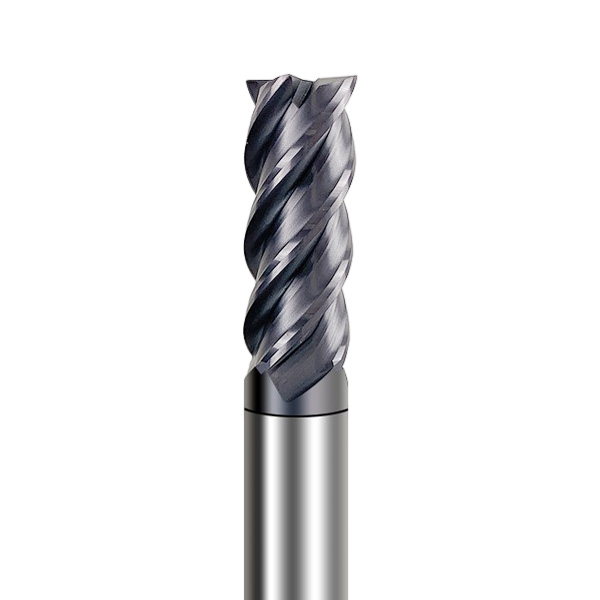
However, it’s crucial not to conflate face mills with end mills. While both may use carbide cutting edges, carbide end mill cutters are designed for peripheral and axial cutting simultaneously (plunging, slotting, contouring), whereas face mills excel only in axial-facing operations.
That said, strategic synergy between the two is powerful:
Use a 45° face mill for rapid material removal.
Switch to a high-performance carbide end mill cutter (e.g., variable helix, corner radius) for detailed features, slots, and tight-radius pockets.
Finish critical edges with a 90° face mill or a square-end carbide end mill for micron-level accuracy.
This tiered approach maximizes productivity while preserving tool life across your entire cutting tool inventory.
From a financial standpoint, 45° face mills often deliver lower cost per part in high-volume scenarios:
Longer insert life due to reduced shock loading.
Higher feed rates enabled by stable cutting forces.
Fewer scrapped parts from chatter-induced surface defects.
However, if your application demands geometric precision that only a 90° face mill can provide, the added cost is justified. Always calculate TCO—not just upfront tool price—by factoring in:
Cycle time savings
Insert changes per shift
Rework or inspection fallout
Machine wear over time
Many shops using premium carbide end mill cutters report that investing in the right face mill upfront reduces downstream wear on their more expensive end mills—a hidden but significant ROI.
There’s no universal “best” between 90° and 45° face mills. The optimal choice depends entirely on your part geometry, machine capabilities, material, and production goals.
As a professional machinist or manufacturing engineer, your role isn’t just to remove material—it’s to remove it intelligently. That means matching tool geometry to process requirements, leveraging the strengths of both face mills and carbide end mill cutters, and continuously refining your strategy based on empirical data from the shop floor.
Whether you’re facing a titanium aerospace bracket or an aluminum enclosure for consumer electronics, understanding the nuanced trade-offs between 90° and 45° face mills empowers you to make decisions that boost quality, reduce waste, and keep your spindle humming smoothly—shift after shift.
person: Mr. Gong
Tel: +86 0769-82380083
Mobile phone:+86 15362883951
Email: info@jimmytool.com
Website: www.jimmytool.com
