

What Is a Face Milling Cutter? A Professional’s Guide to Precision, Performance, and Carbide End Mill Cutter Integration
Date:2025-12-21Number:1804In the world of precision machining, few tools are as fundamental—and yet as frequently misunderstood—as the face milling cutter. Whether you’re a seasoned machinist, a manufacturing engineer, or a procurement specialist sourcing high-performance tooling, understanding what a face milling cutter truly is—and how it relates to other critical cutting tools like the carbide end mill cutter—can significantly impact your shop’s efficiency, surface finish quality, and bottom line.
This article dives deep into the anatomy, applications, material science, and strategic selection criteria of face milling cutters, while also clarifying their relationship (and distinctions) with carbide end mill cutters. Written from the perspective of professionals who live and breathe metal removal every day, this guide is designed not just to inform—but to empower smarter, data-driven decisions in real-world machining environments.
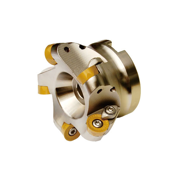
At its essence, a face milling cutter is a rotary cutting tool specifically engineered to machine flat surfaces perpendicular to the axis of rotation—commonly referred to as “facing.” Unlike end mills that cut primarily with their end tips and flutes along the side, face mills engage the workpiece with multiple inserts mounted radially around a central body. The cutting action occurs predominantly on the face (top surface) of the workpiece, delivering high material removal rates (MRR) and excellent surface finishes in a single pass.
These cutters are typically used on vertical or horizontal machining centers, CNC mills, and even manual milling machines when large, flat surfaces need to be prepared quickly and accurately—such as mold bases, fixture plates, or structural components in aerospace and automotive industries.
Key characteristics include:
Multiple replaceable inserts: Usually indexable carbide tips that can be rotated or replaced without discarding the entire tool.
Large diameter-to-length ratio: Optimized for stability during broad-surface cuts.
Shallow axial depth of cut (DOC): Typically 0.5 mm to 3 mm, depending on material and machine rigidity.
High radial engagement: Often 50–100% of the cutter diameter.
Because of their design, face milling cutters excel in roughing, semi-finishing, and even finishing operations—especially when paired with modern insert geometries and coatings.
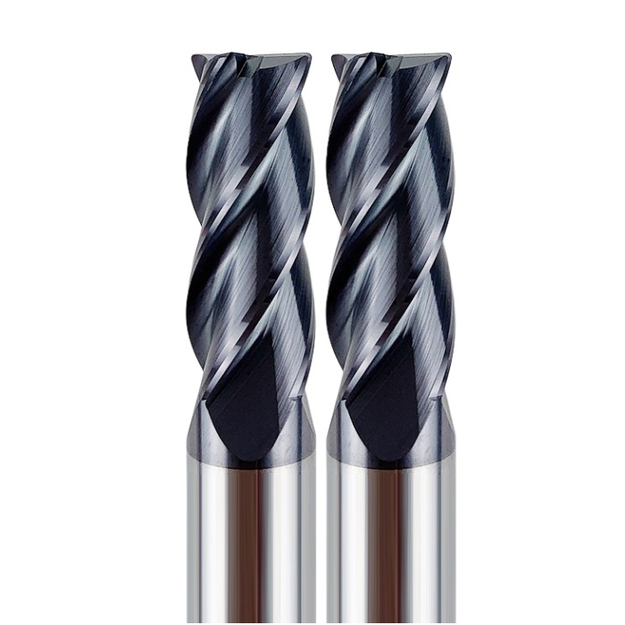
One of the most common points of confusion among new machinists—and even some seasoned professionals—is the functional overlap (and divergence) between face milling cutters and carbide end mill cutters.
A carbide end mill cutter is a solid or brazed tool made from tungsten carbide, designed for profiling, slotting, pocketing, and contouring. While certain end mills can perform light facing operations (especially flat-end types), they are not optimized for large-area surfacing. Attempting to face-mill a 200mm x 200mm plate with a 12mm carbide end mill would be inefficient, time-consuming, and potentially damaging to the tool due to excessive heat buildup and chatter.
Conversely, face milling cutters are rarely used for intricate 3D contours or deep slots—their geometry simply doesn’t allow it. They lack the side-cutting capability and fine tip definition of a carbide end mill cutter.
Strategic Insight: Smart shops use both tools synergistically. A face mill quickly levels a raw casting or billet to datum, then a carbide end mill cutter takes over for detailed features. This division of labor maximizes throughput while preserving tool life.
Moreover, many modern face mills now incorporate carbide inserts that share the same advanced substrate and coating technologies found in premium carbide end mill cutters—such as nanostructured PVD coatings, micro-grain carbide substrates, and edge-prep treatments for thermal shock resistance. This convergence underscores a broader trend: performance is increasingly defined by material science, not just geometry.
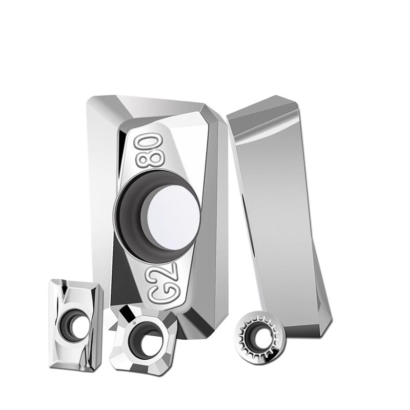
While older face mills used high-speed steel (HSS) or even brazed carbide tips, today’s high-productivity environments demand indexable carbide inserts. These inserts offer:
Higher cutting speeds (up to 3x faster than HSS)
Extended tool life under heavy interrupted cuts
Consistent repeatability through multiple indexing positions
Cost efficiency via insert replacement rather than whole-tool discard
Crucially, the same R&D that drives innovation in carbide end mill cutter performance—grain size refinement, cobalt content optimization, multi-layer AlTiN or TiSiN coatings—directly benefits face milling inserts. For example, a face mill running in hardened tool steel (50–60 HRC) might use the same grade of carbide insert as a finishing carbide end mill cutter in the same application.
This cross-pollination means that when evaluating a face milling system, professionals should consider the insert’s compatibility with their existing carbide end mill cutter inventory. Standardizing on a few high-performance carbide grades across both tool types simplifies logistics, reduces inventory costs, and ensures consistent machining behavior.
Choosing a face mill isn’t just about diameter and number of inserts. Seasoned practitioners evaluate several interdependent variables:
Positive vs. Negative Rake: Positive rake reduces cutting forces (ideal for less rigid setups); negative rake offers edge strength for tough materials.
Chip Breaker Design: Critical for managing swarf in aluminum vs. stainless steel.
Coating Type: TiAlN for high-temp alloys; uncoated polished carbide for non-ferrous metals to prevent built-up edge.
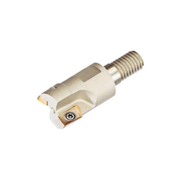
Shell vs. Arbor-Mount: Shell mills offer modularity; arbor types provide better balance at high RPM.
Helix Angle & Lead Angle: A 45° lead angle (most common) balances chip thinning and radial force distribution. High-feed face mills may use 10°–15° for aggressive chip loads.
Roughing: Use cutters with fewer, stronger inserts and high feed per tooth (e.g., 0.3–0.5 mm/tooth).
Finishing: Opt for dense insert counts, wiper geometries, and tight runout tolerances (<0.01 mm).
Verify spindle power, torque curve, and maximum RPM. A 200mm face mill running at 800 RPM in Inconel demands far more torque than a 50mm mill in aluminum at 10,000 RPM.
Consider a Tier-1 aerospace supplier machining 7075-T6 aluminum plates (600mm x 400mm x 50mm). Their goal: achieve ±0.05mm flatness and Ra 1.6 µm surface finish in minimal cycles.
Old Approach:
Used a 20mm solid carbide end mill cutter with 4 flutes.
Required 12 passes at 0.5mm DOC.
Cycle time: 22 minutes.
Tool wear after 3 parts.
New Approach:
Switched to a 125mm face mill with 8 polycrystalline diamond (PCD)-tipped carbide inserts.
Single pass at 1.2mm DOC, feed rate 4,500 mm/min.
Cycle time: 3.5 minutes.
Insert life: 120+ parts.
The ROI was immediate—not just in time savings, but in reduced scrap from thermal distortion (fewer passes = less heat input). Note: while PCD isn’t typical for steel, this example highlights how material-specific insert choices—akin to selecting the right carbide end mill cutter for an application—drive results.
Even experienced teams fall into traps:
Overhanging the cutter: Reduces rigidity, induces vibration. Keep overhang <1.5x cutter diameter.
Ignoring insert indexing sequence: Leads to uneven wear and poor surface finish.
Mismatching coolant strategy: Through-spindle coolant is often unnecessary in dry or air-blast face milling of aluminum—but essential in titanium.
Using worn inserts for finishing: Wiper inserts lose effectiveness after just 10–15 minutes in abrasive materials.
Remember: a face mill is only as good as its weakest insert. Regular inspection and proactive replacement are non-negotiable.
Emerging trends are blurring the lines between traditional categories. Some manufacturers now offer hybrid face mills with integrated sensors that monitor vibration, temperature, and wear in real time—data that can be correlated with carbide end mill cutter performance across the same job. Digital twins of toolpaths allow simulation of face milling forces before metal is ever cut, optimizing parameters alongside end milling operations.
Moreover, additive manufacturing is enabling topologically optimized face mill bodies—lighter, stiffer, and dynamically balanced beyond what casting or forging could achieve. These innovations ensure that face milling remains not just relevant, but increasingly intelligent.
To ask “What is a face milling cutter?” is to open the door to a deeper conversation about machining philosophy. It’s not merely a chunk of steel with inserts bolted on. It’s a precision-engineered system that must harmonize with your workpiece material, machine dynamics, fixturing strategy, and downstream processes—including those performed by your carbide end mill cutters.
For professionals, mastery lies in seeing the entire workflow. A well-chosen face mill sets the stage for everything that follows. It establishes flatness, controls residual stress, and defines the foundation upon which complex geometries—machined by your finest carbide end mill cutters—are built.
So the next time you reach for a face mill, remember: you’re not just removing material. You’re setting the standard.
person: Mr. Gong
Tel: +86 0769-82380083
Mobile phone:+86 15362883951
Email: info@jimmytool.com
Website: www.jimmytool.com
