

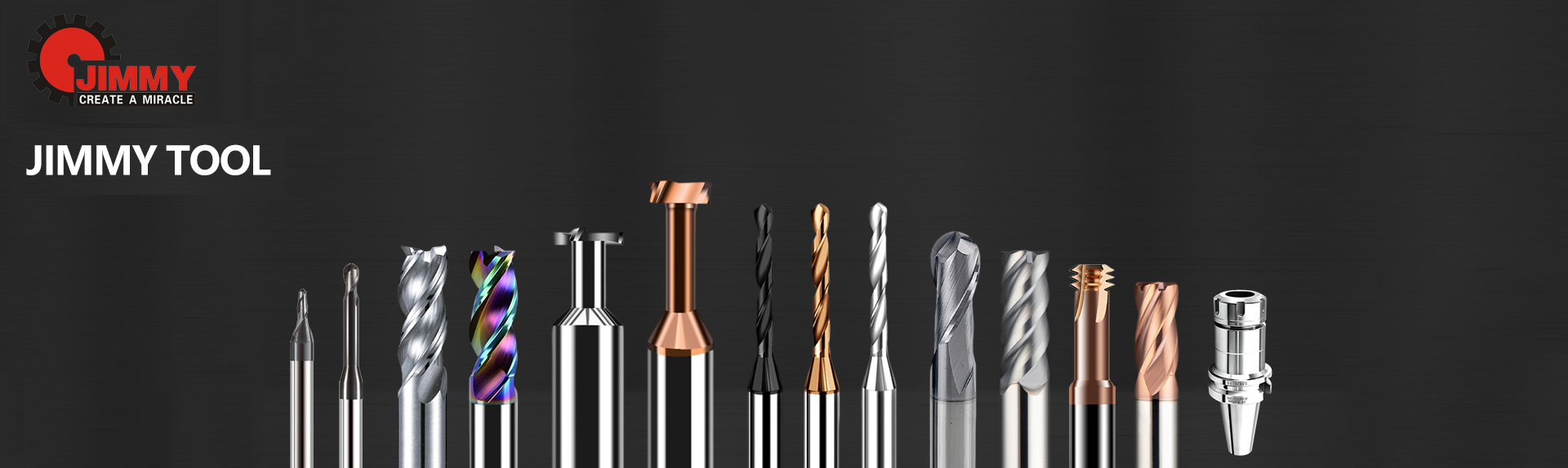
Center Drill Angle Guide: 60° vs 75° vs 90° for CNC Machining Accuracy
Date:2026-05-28Number:1181A center drill may be small, but its tip angle dictates where the hole actually ends up. Choose the wrong angle, and you risk drill wander, poor coaxiality, and shortened tool life before the main drill even enters the cut.
This guide explains how 60°, 75°, and 90° center drill angles differ in geometry and performance, how to match the angle to your material and machine, and where operators often go wrong. By the end, you’ll have a clear selection framework to make every hole start exactly on target.
A center drill angle is the included angle of the cone-shaped cutting tip on a center drill. It is measured across the two cutting edges, just like a standard twist drill point. However, unlike a long twist drill, a center drill is a short, stiff tool designed for one job: to initiate a perfectly centered, clean entry point before a deeper or larger drill takes over.
The tip angle determines three things at once:
How the tool engages the material surface;
How the cutting forces are distributed;
What kind of seat or guide it prepares for the next operation.
In machining practice, 60°, 75°, and 90° are the angles you will encounter most often, and they each solve a different set of engineering challenges.
When a drill enters a flat surface off-center, the position error can propagate through every subsequent operation. In multi-axis CNC work, a 0.05 mm error at center stage can become a 0.2 mm hole-position error at full depth—enough to scrap a high-value component.
Selecting the right center drill angle controls several accuracy factors directly:
Drill deflection minimization: The center drill’s short flute length and suitable tip angle locate the hole axis exactly, letting the following drill follow a true path.
Coaxiality: A well-formed center cone ensures that the main drill’s chisel edge seats at the very bottom, not on the cone wall, reducing wobble.
Initial cutting force distribution: A shallower angle tends to increase axial force but improves radial stability; a sharper angle reduces thrust but is weaker.
Thermal stability: The angle affects chip formation and heat concentration at the tip during the brief spotting cycle, especially in materials that work-harden.
From a production standpoint, an incorrectly chosen angle can cause:
Premature tip chipping, requiring more frequent tool changes;
Bell-mouthed or oval start holes, which degrade roundness;
Higher scrap rates in batch runs where tolerance is tight.
👉 View Carbide Drill Bits
👉 Contact Engineering Support
The engineering behavior of each angle stems from the interaction between tool geometry and the material being cut. Here is a detailed comparison before we dive into each one.
| Angle | Tip Geometry | Cutting Action | Typical Depth | Heat & Force | Best Suited For |
|---|---|---|---|---|---|
| 60° | Sharp, narrow wedge | Low thrust, easy penetration, small contact zone | Shallow to medium cone | Low cutting force, lower edge strength | General centering, non-ferrous, mild steels, lathe centers |
| 75° | Moderately blunt, reinforced point | Higher thrust but stronger edge, improved heat dissipation | Medium cone | Balanced force, good for hard materials | Stainless steel, alloy steels, tougher alloys |
| 90° | Broad, flat cone | Very stable, large contact area, high radial force | Shallow seat only | Higher friction at tip, poor axial guiding | Countersinking, seat preparation, sheet metal locating |
60° Center Drills – Fast, Efficient Alignment
The narrow 60° cone resembles a standard lathe center. It penetrates the material with minimal axial resistance, so it is easy on smaller machines and ideal for spotting in non-hardened metals. The downside is that the sharp tip has less mass behind the cutting edge, making it more prone to micro-chipping if runout is present or if the workpiece surface is irregular.
75° Center Drills – Toughness for Hard Materials
By widening the point angle to 75°, the cutting edges become more robust. The larger cross-section behind the edge absorbs more heat and withstands higher cutting pressures without deforming. This is critical in stainless steels and high-strength alloys, where heat concentrates quickly and work-hardening risk is high. A 75° angle also helps break up the chip slightly, reducing the chance of a built-up edge.
90° Center Drills – for Seats, Not Depth
A 90° tip creates a conical seat that is very wide relative to its depth. Its primary function is not to guide a twist drill but to create a flat, stable surface for a countersunk fastener head or to precisely locate a component on a fixture pin. Because the cone is so open, it provides little axial guidance for a following drill; using it as a starter for a 118° or 135° drill would mean the drill’s chisel point engages on a wide flat rather than inside a narrow cone, increasing walk risk.
Angle selection is an engineering decision based on material hardness, machine condition, and what happens after center drilling. Use the following practical guidelines and parameter ranges.
Aluminum, brass, plastics: 60° — low thrust, fine finish. Run at 1,500–4,000 RPM (smaller drills higher), feed 0.02–0.08 mm/rev.
Mild steel (up to ~200 HB): 60° or 75° — 60° for light depth, 75° for heavier starts. RPM 1,000–2,500, feed 0.03–0.10 mm/rev.
Stainless steel (304, 316): 75° recommended — prevents early edge break down. RPM 500–1,200, feed 0.02–0.06 mm/rev. Use coolant at rich concentration.
Alloy steel, pre-hardened (30–40 HRC): 75° mandatory. Reduce RPM to 400–900, feed 0.02–0.05 mm/rev, ensure rigid setup and through-coolant if possible.
CNC mill with low runout (TIR < 5 µm): Any angle works; 75° gives extra tool life.
Manual lathe or drill press with moderate play: Prefer 60° — it is more forgiving of slight misalignment and reduces sudden edge fracture risk.
High-speed spindle with shrink-fit holder: 75° benefits from stiffness and produces consistent cones in hard metal.
This is often the most overlooked criterion. The center drill angle must be greater than or equal to the point angle of the subsequent twist drill. If you use a 135° drill, the center cone should be at least 135° (typically 140–142° spot drill) so the twist drill’s chisel edge lands at the cone’s very tip, not on the wall. Standard 60° center drills are thus suited for 118° drills. For 135° drills, you either use a special 135° spot drill or rely on a spot drill with a wider angle.
This is covered in depth in the next section.
Low volume, prototyping: A 60° center drill in HSS handles most common jobs.
Medium to high volume CNC: Carbide center drills with 75° tip and coating (TiN or TiAlN) reduce tool changes and maintain consistent spot depth.
Mass production of shafts: Integrated combination center drills (pilot + 60° cone) on automatic lathes, matched with machine specifications.
👉 View Carbide Drill Bits
👉 Contact Engineering Support
Getting the center drill angle right is not just about the spot itself; it is about how the drill point that follows it interacts with the cone.
| Main Drill Point Angle | Recommended Center/Sport Drill Angle | Reason |
|---|---|---|
| 118° (standard) | 60° or 90° | A 60° cone guides the 118° point nicely; a 90° spot also provides full contact for the chisel. |
| 135° (split point, hard material) | 135°–142° spot drill | The center cone must be wider than the drill point so the drill tip contacts the cone apex first. A 60° center drill would force the 135° drill to contact on its outer edges, causing wobble. |
| 140° (specialty) | 140°–150° spot drill | Same logic — avoid the drill riding the wall of the center cone. |
For precision CNC work, use a spot drill with an angle slightly larger than your main drill (e.g., 140° spot for a 135° drill). For lathe center holes meant to hold a live center, a classic 60° center drill is the correct choice because machine centers have 60° points.
These two tools are frequently confused because they both create starting features. However, their geometry and purpose differ significantly.
| Feature | Center Drill | Spot Drill |
|---|---|---|
| Primary design | Create a 60° center hole for lathe work or as a pre-hole for a drill ≤ its web thickness. | Create a shallow dimple wider than the following drill’s web, ensuring precise XY location. |
| Tip geometry | Small pilot diameter followed by 60° cone | Short, straight flute, typically 140° or 142° point, very rigid |
| Depth of cut | Can go deeper to form a full center seat | Very shallow (just enough to mark the spot) |
| Typical use | Lathes, shaft manufacturing, larger center holes on manual mills | CNC milling, high-precision hole positioning for drills of any point angle |
| Rigidity | Lower due to small pilot neck | High, no neck – solid shank to tip |
Use a center drill when you need a cone that will accept a 60° lathe center or when the following drill has a 118° point and you want to drill a pilot hole at the same time. Use a spot drill for CNC milling with drills having point angles 135° and above—it purely marks the position with zero risk of breaking a fragile pilot tip.
What happens: The main drill wobbles, drilling off-position.
Correction: Always ensure the center cone is wider than the drill point. For 135° drills, use a spot drill, not a 60° center drill.
What happens: The thin pilot tip breaks off inside the part.
Correction: Center drills are only for starting. Depth of cut should not exceed the tapered portion of the tool. Use a proper twist drill for deeper holes.
What happens: One lip bears all the load, causing micro-chipping at the 60° tip.
Correction: Check runout with a dial indicator. If TIR exceeds 0.01 mm, address holder or collet issues before running carbide center drills.
What happens: High feed fractures the tip in hard materials; low feed rubs, work-hardens the surface (particularly in stainless).
Correction: Use a chip load of about 0.02–0.05 mm/rev for small center drills (Ø3–6 mm). Adapt based on material—if chips are dusty or tool screams, adjust feed.
What happens: Tip overheats, losing hardness, and built-up edge forms in sticky materials.
Correction: For stainless and alloy steels, direct a continuous coolant stream exactly at the spot. Oil-based mist or emulsion is more effective than dry air.
What happens: The main drill deflects dramatically on entry.
Correction: Use a center drill or spot drill to create a flat starting seat before drilling on rough or slanted faces.
The proper center drill angle improves process reliability across a range of industries:
Automotive drive components: Shaft centering for spline cutting, bearing journal preparation.
Aerospace structural parts: Accurate bolt pattern starts in titanium and alloy steel before high-precision drilling.
Mold & die: Center holes on pre-hardened blocks to locate ejector pin holes.
Medical implants: CoCr or Ti6Al4V parts require robust 75° or carbide center tools with coolant.
General machine building: Reliable lathe center holes for turning and grinding operations.
In CNC production, reducing scrap starts at the first cut—and the center drill is often that cut.
Jimmy Tool supplies industrial-grade center drills manufactured from HSS and solid carbide, engineered for consistent spotting performance in CNC lathes, mills, and transfer lines. Our product line includes standard 60° center drills, 75° designs for hard metal, and 90° variants for countersinking applications.
We support OEM custom tooling, allowing you to specify geometry, coating (TiN, TiAlN, and others), and batch quantities. Our quality system ensures stable delivery for manufacturers demanding repeatable tool life.
👉 View Carbide Drill Bits
👉 Contact Engineering Support
What is the most common center drill angle?
60° is the standard for general machining, lathe centers, and pilot hole preparation.
When should I use a 75° center drill?
Select 75° when drilling stainless steel, alloy steel, or tough metals—it provides stronger edges and better heat resistance.
Can I use a 90° center drill to start a hole?
It’s not recommended for deep hole guidance. 90° center drills are better suited for creating a flat seat for countersunk fasteners or for locating on a pin, not for axial alignment of a twist drill.
What is the difference between a center drill and a spot drill?
A center drill has a small pilot and a 60° cone, designed for lathe centers or as a combined pilot drill. A spot drill is a short, rigid tool with a wider point angle (often 140°) used in CNC milling to precisely locate a hole and provide a chamfer.
How deep should I center drill?
Drill only deep enough to create a full cone—usually 1 to 1.5 times the pilot diameter for a standard center drill. Never plunge beyond the taper into the pilot neck unless you are intentionally drilling a through-hole of that size.
What RPM should I use for a center drill?
RPM depends on diameter and material. For a 6 mm HSS center drill in mild steel, around 1,500–2,000 RPM is typical. In stainless steel, reduce to 600–1,000 RPM. Always follow the cutting speed formula: RPM = (VC × 1000) / (π × D), with VC 15–30 m/min for HSS in steel.
Do carbide center drills improve accuracy?
Yes, especially in high-volume CNC and hard materials. Carbide holds a sharper cutting edge longer, reducing the risk of the tip deforming under heat, which keeps the cone geometry consistent.
person: Mr. Gong
Tel: +86 0769-82380083
Mobile phone:+86 15362883951
Email: info@jimmytool.com
Website: www.jimmytool.com


